Sand cores are a crucial component in the sand casting process. They create internal cavities and detailed features within metal castings that cannot be generated using only a two-piece mold. The core forms negative space within the casting that would otherwise be impossible.
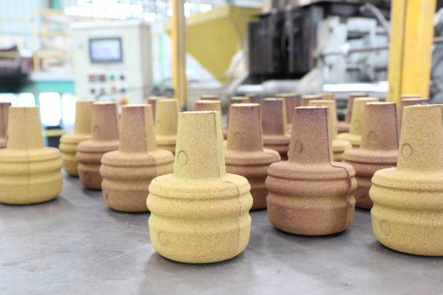
Sand cores achieve this by placing temporary placeholders of bonded sand into the mold cavity, which displace liquid metal when the mold is poured. This sand is later removed through a designed opening in the casting, leaving behind hollow internal geometry.
Core Properties
Sand cores must satisfy several essential requirements:
- Permeability - The core sand needs sufficient venting to allow gases to escape during molten metal pouring. It prevents gas defects.
- Collapsibility - Following solidification, the sand core must be removable from the casting through physical collapse or dissolution using water or other agents.
- Refractoriness - Heat resistance is required so the core does not melt, fuse or chemically react with the molten pouring metal.
- Strength - Cores must withstand forces from metallostatic head pressure and thermal expansion during solidification.
Sand Core Manufacturing
There are two main methods used to manufacture sand cores:
Hot Box - A heated metal pattern tool compacts and cures thermoset resin-coated sand into rigid cores. Often phenolic urethane binders are used. Simple core boxes make short lead time and design changes possible.
Cold Box - Sand is coated with a gas-cured resin and blown into a room-temperature core box tool. The curing gas activates the resin to harden the core once formed. This method enables complex core geometries.
In both cases, the cured sand cores are aged to develop strength before use in casting fully. For high production, automated core shooting machines are used. But short-run custom sand cores utilize hand-packed core boxes.
Core Design Principles
Several vital guidelines govern core design:
- Simple shapes - Complex undercuts and deep recesses make cores prone to breakage and defects. Gradual transitions and tapers should be used.
- Uniform wall thickness - Drastic changes in casting wall thickness due to inconsistent core sizes will lead to defects and hot tears.
- Minimal projections - Long thin sections of cores are weak and may fuse into the casting. Short, stout core prints should be utilized.
- Accessible contours - The core must be reachable through the mold opening for dismantling and removal from the solidified casting.
- Venting - To minimize gas defects, adequate venting must be designed into the core using sand additives, vent wires, and proper gating.
- Alignment - Core prints and locating features should be provided to position the core within the mold cavity accurately.
Applications of Cores
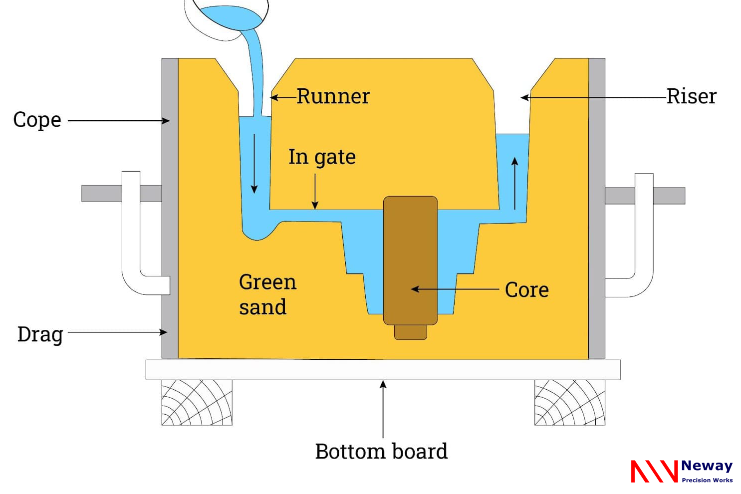
Sand cores enable the manufacture of castings with unachievable geometry using an essential cope and drag mold tool. At the same time, it can also simplify or replace the row position of die-casting parts to achieve higher complexity. Some examples include:
- Internal passages - Cylindrical cores create hollow internal bores for hydraulic valves and cylinders.
- Complex chambers - Cores form intake and exhaust ports with complex contours in engine cylinder heads.
- Undercut features - Collapsible sand cores allow castings with recesses, slots, and undercuts.
- Hollow sections - Cores spanning the complete mold create structural castings with hollow interior walls.
- Heavy sections - Cores can locally increase casting section thickness to improve stiffness and strength.
- Intricate channels - Branched coolant passages inside castings are made using multi-core assemblies.
- Cost reduction - Cores reduce machining by creating cast-in holes and bosses rather than removing material. Manufacture of complex, undercut castings by foundry casting can significantly reduce initial tooling costs
Proper application of sand cores enables many functions critical to part performance and quality. Core selection should be optimized based on production volumes, lead time, cost, design complexity, and required casting properties. With the right core technology, high-integrity castings can be produced.
"Thanks to Neway's custom sand casting expertise, we were able to rapidly prototype our breakthrough power tool design and bring it to market ahead of schedule. Their craftsmen worked tirelessly to deliver flawless castings and injection molded parts that exceeded our strict specifications. And their experience optimizing designs for manufacturability was invaluable. I'm not sure where we'd be today without their partnership in creating this revolutionary product." - Steve J., AQUMMA Power Tools
评论
发表评论